Handwired Alpha
The mechanical keyboard community, which is well represented on Reddit, is a thriving little niche community of total keyboard nerds. And within that community, there are numerous sub-cultures: the keyboard collectors, the artisan keycap fans, the switch hackers, and–and this is the subject of this post–the builders.
Yes, builders–those slightly crazy people who take great pleasure in constructing their very own customized, personalized keyboards.
Now, within the building community there’s a few routes.
First, it’s important to understand the essential bones of a keyboard. A typical build requires:
- The switches
- Keycaps
- A controller
- Some mechanism to wire everything up
- A switch plate
- A case, in which to put everything
The simplest route to fulfilling all these requirements is to buy a kit, which typically includes a PCB, which is used to wire the switches together to a controller to form the essential bones of the board, and the case, where everything lives. The kit might also include switches and keycaps, or they might be sourced separately. The builder then mounts the switches on the plate, solders them to the PCB, and then puts everything together.
The most masochistic do nearly everything from scratch. Forgoing the PCB, the builder buys a controller (typically an Arduino of some kind), sources or builds a case, and solders the whole thing together by hand with wires and diodes.
Well, you can imagine what I did.
Handwired Alpha - Some basic keyboard theory
A keyboard is a surprisingly simple little device. The basic operation is as follows:
- The switches are wired together into a matrix of rows and columns.
- The controller sends a signal down each column (or row).
- The controller then checks for a return signal down each row (or column).
- This information determines which key(s) have been pressed.
- The controller then sends the keycode to the host machine.
Simple!
So, to construct a keyboard, one must:
- Solder the switches into a matrix of rows and columns.
- Solder the matrix to the controller.
- Program the firmware of the controller so it understands the key matrix.
- Then stuff everything into a case, grab a beer, and call it a day!
The only slightly tricky bit is the matrix itself.
For reasons that are very nicely explained by this write-up, each switch must be attached to a single diode that ensures that current can only cross the switch in one direction. This arrangement ensures that multiple keys pressed together don’t result in the matrix being misinterpreted by the controller.
The typical arrangement is to introduce a diode which allows current to flow from the column to the row, although either arrangement is workable so long as all diodes are arranged the same way.
The open source community has neatly solved the challenged of keyboard firmware. So long as the controller makes use of a supported Arduino chipset, the open source QMK firmware is an incredibly capable solution. To make use of QMK, you simply configure it to understand the key matrix layout, and the associated GPIO pin assignments on the controller. That information is enough to allow QMK to power the keyboard!
Handwired Alpha - Design
Key layout
For my first keyboard I wanted to come up with a design that was unique enough to justify a build, but still practical and useful. After seeing an HHKB layout, I also decided I didn’t want to get locked into a traditional rectangular key layout. I wanted something different.
There are a few things about my target use case for this keyboard, and my own typing habits, that informed the layout I chose.
First, this keyboard would be used at work, where I no longer code professionally. Instead, my keyboard is used mostly for writing prose, in the form of email, documents, and so forth. This fact allowed me to sacrifice dedicated function keys and the grave/tilde key, as I knew I wouldn’t be using them heavily.
Second, my typing style has evolved to rely entirely on my left hand to operate the Alt, Control, and Super keys. Those keys on the right side of the keyboard see no use during my normal day to day activities.
Finally, I do tend to use the arrow cluster and page up/down keys a fair bit. I knew I’d want to preserve them in lieu of a true 60% layout.
What I ultimately arrived at is this somewhat peculiar design:
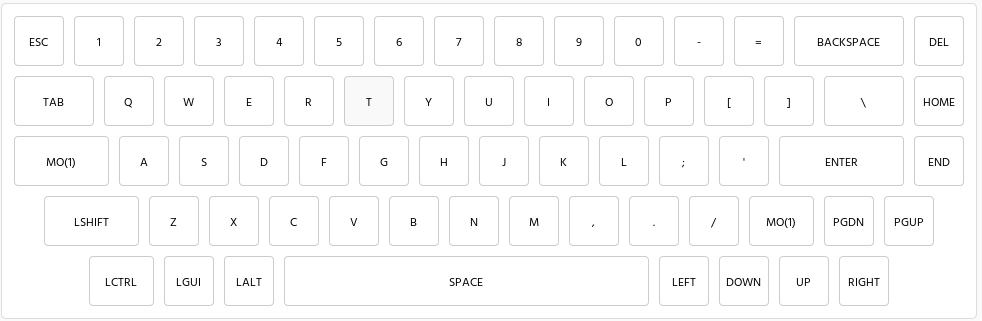
I developed this using the Keyboard Layout Editor, which is an enormously useful tool!
As you can see, by removing the right-hand meta keys I was able to use that space for other keys that I find most useful. In particular, Vim users will recognize the arrow key arrangement, which mirrors the hjkl navigation cluster. I then adjusted the key dimensions to produce a symmetric, tapered profile across the board.
In addition, I’ve defined a layer that includes the function keys, plus some useful media keys1:
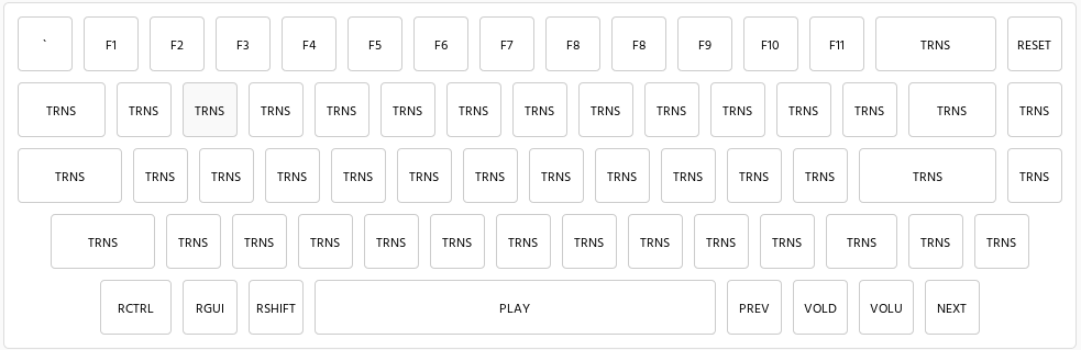
In general this has proved mostly successful, though I gotta admit, the left control key positioning is a little tricky to adjust to (I’ve definitely missed it a few times!) and I do miss the F12 key in Linux (which I use to open Guake).
Case
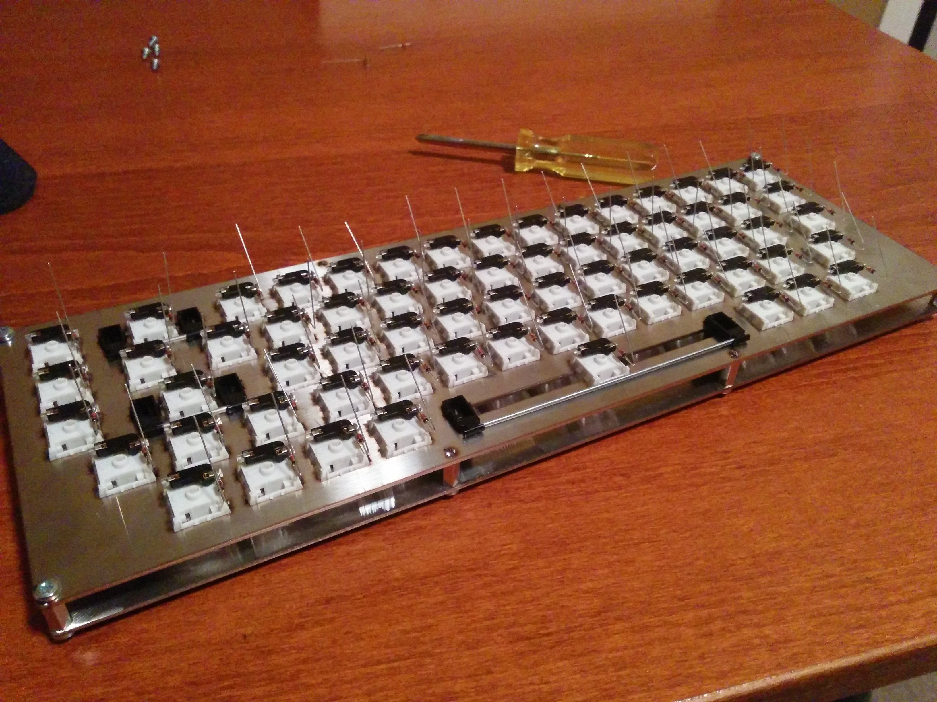
For the case my primary goal was to build something cheap, flexible, and easy to assemble. I knew that meant a sandwich case design, though in the interest of reducing costs, I left out the interior layers, instead opting for an open plate construction. The result is what I charitably think of as an industrial-style look that let’s you catch a glimpse of the guts of the thing.
Hotswappable
I feel the most interesting aspect of this keyboard design is the entirely hot swappable nature of the build. Rather than soldering the matrix directly to the switches, I used Kailh hotswap sockets, which means the switches themselves can be easily swapped out.
In addition (and I have much more mixed feelings about this), the controller is connected to the matrix using a set of low profile board-to-board mating sockets and pins. This means the board can be easily detached from the matrix, which makes it possible to replace it or reuse the board in another project in the future.
Finally, the use of a USB breakout board with a custom made cable allows me to easily remove the case and detach the breakout board without disturbing the rest of the build.
This construction provides a couple of benefits. First, again, it allows repair or replacement of components and so forth, which is nice. However, for this paranoid first timer solderer, it also meant I could avoid soldering directly to delicate components. Other than soldering the headers to the USB breakout board and controller, all other joints involved cheap, replaceable sockets and pins.
In hindsight, I think this was a great design choice, with the exception of the hotswappable controller. As we’ll get to later, that choice resulted in the case not having enough space, due to the height of the combination of controller plus socket plus pins, which meant I had to get taller standoffs to complete the assembly.
-
This image doesn’t actually reflect the final layout, as I ended up mapping Fn-PgUp to Mute, and configured the Esc key to be the QMK Grave-Esc hyper key, among other minor tweaks. ↩
Handwired Alpha - Supplies, components, and equipment
Supplies
This keyboard is my very first electronics project. Prior to building Alpha, the only soldering I’ve done was to make the odd custom audio cable. As a result, I was… well, literally ill-equipped to take on his project, which required some serious investment.
Here are some of the essentials I picked up. All part numbers can be found on Digikey, which I used as my primary electronics supplier:
- Soldering Iron (243-1156-ND)
- Soldering Iron Stand (243-1156-ND)
- Hemostat (243-1168-ND)
- Multimeter (MN35-ND)
- Desolder Braid (243-1185-ND)
- Desolder Pump (243-1183-ND)
- Lead bending tool (1568-1132-ND)
- Fume absorber (243-1318-ND)
In addition, I took advantage of a cutting mat that was already in our possession as a work surface.
I also needed some consumables for assembly:
- Magnet Wire (1568-1088-ND)
- Solder (RASW.0201OZ-ND)
A couple of things to note, here.
First, I used magnet wire for the assembly. This was a very good choice. Magnet wire has a couple of incredibly useful properties:
- It is coated with an insulation that burns off with a hot soldering iron and a little solder. This meant no stripping of insulation (except for circumstances where I really wanted to avoid overheating). I could just solder directly, confident that there wouldn’t be unexpected shorts.
- Because it’s solid core wire and not stranded, it can be shaped easily. In the final build you can see how I’ve arranged the wire into clean right angles that would’ve been impossible had I used insulated, stranded wire.
Second, I opted for leaded 63/37 rosin activated solder. This stuff melts clean, freezes fast and consistently, and is generally just very easy to work with.
Components
Just to review, a hand wired keyboard is built of a few essential parts that you have to build or source, including:
- Switches - you gotta press something
- Keycaps - no one wants to just press a switch
- Case - everything’s gotta go in something
- The keyboard controller - so the switches have something to talk to
- Stabilizers - so your spacebar isn’t wobbly
- Diodes - to ensure multiple key presses don’t confuse the controller
- Hardware - you gotta piece that case together with something
Obviously a lot of the nuance in a build is selecting these parts so in the following sections I’ll go over those choices.
Switch selection
Probably the two most important parts decisions when building a keyboard are the switches and the keycaps.
In the case of the former, the best thing you can do is pick up a switch tester, which is a little selection of switches mounted in an acrylic block which allows you to feel out which switches might be best for you.
To narrow it down it’s important to understand the three main classes of switch: linear, tactile, and clicky. All mechanical switches actuate part way through the press, which allows the typist to register a key press without bottoming the key out.
A linear switch provides no explicit tactile feedback during the press. Instead, you just feel some additional resistance as the spring in the switch compresses.
A tactile switch includes the feeling of a “bump” on the way down–a brief increase of resistance followed by a linear-style press through to bottoming out.
A clicky switch behaves like a tactile switch, but includes an audible click to indicate the switch has actuated.
Among these classes things vary widely, from spring weight to tactile bump intensity and click loudness. There’s a lot to choose from!
Since I was building a keyboard for office use, I wanted to avoid clicky switches. But I do appreciate some amount of tactile feedback. Consequently, I decided to buy a KBDfans tactile switch tester.
Once the tester arrived, I eventually settled on the Kailh Hako Violet switch, which is a fairly light switch with a nice, light, tactile bump.
Keycap selection
Keycaps are an interesting challenge to choose. I won’t go too deep into the nuances, as there’s many of other resources out there that explain the variables, but in broad strokes you have to choose between keycap materials (ABS or PBT), printing method (laser etched, dye sublimated, or double shot), key profile (uh.. lots), key profile, and board compatibility.
The material tends to dictate the general feel of the keycap.
The printing method affects how well the keys wear over time.
Key profile is the shape of the keycap. Many mechanical keyboards include sculpted key profiles, which change row to row and create a curved overall shape to the board. Others (in particular the DSA profile) are flat.
Board compatibility is a function of key layout. For example, my layout includes a 1.75u shift (the standard square keycap is 1u all other keys are measured as a ratio of that base size), which is somewhat unusual. As a result, I needed a keycap set that included a shift key of that size.
And, of course, one can’t discount cost.
In my case, my oddball key layout immediately forced me to select DSA profile caps. Why? Well, because my layout had keys in unusual rows (e.g., the arrow keys on the bottom row), sculpted keycaps would’ve resulted in a weird, inconsistent profile, since the keys on my board would be in the wrong place relative to the normal profile for the caps.
Once I was forced to DSA caps, my options were a lot more limited.
On top of that, some of my key size selections (like the 1.75u shift) limited options further.
Factor in cost (keycaps can get enormously expensive!) and I ended up selecting the KBDfans DSA Lazer Etched 145 key blue and white cap set.
They’re not the highest end caps in the world, and the legends will wear off over time, but they’re still a pretty darn nice set!
Controller
To be honest, controller selection was dictated by two factors:
- I wanted an ATmega32u4 CPU, as that’s very well supported by the open source QMK keyboard firmware.
- I was ordering on Digikey.
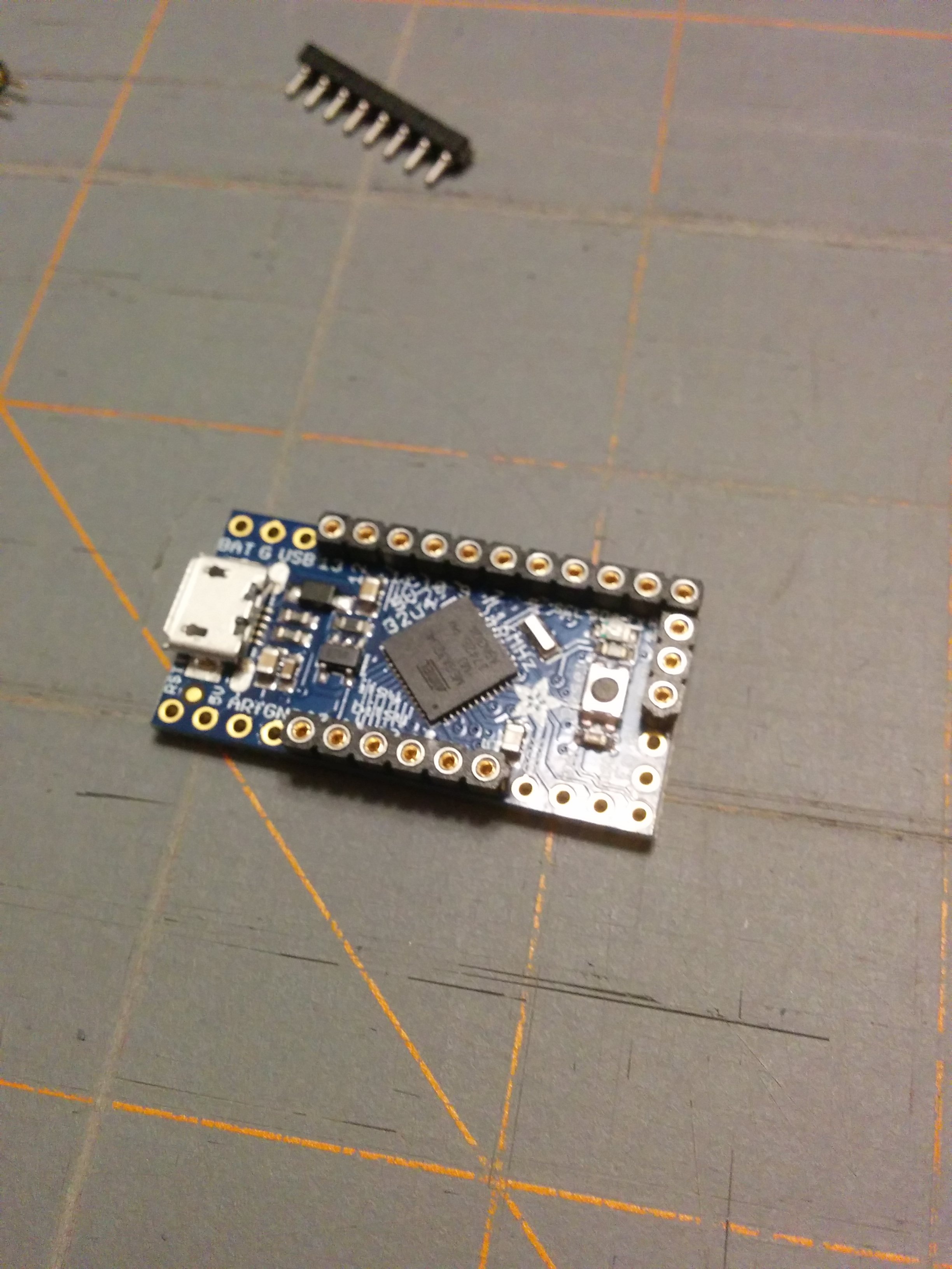
That left me with a single choice: The Adafruit Itsybitsy 5V (1528-2501-ND).
This device worked out great! It has a decent number of pins (23) at a reasonable price point. The only tricky thing was finding a useful pinout using the AVR pin names. Fortunately, the 40percent.club website had a pin mapping, which I’ve happy cribbed and included here:
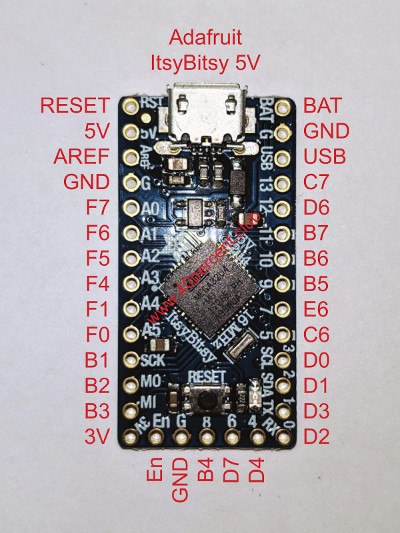
With that the rest was a piece of cake.
Case construction
As I mentioned previously, a sandwich-style case is composed of two pieces: the switch plate and the backing plate (and normally a couple of middle layers, but I skipped those).
I opted for 1.5mm brushed stainless steel, laser cut by Underpressure Welding. They did a wonderful job, though I should’ve asked them not to sand off the burrs that resulted from the cut, as the bottom plate ended up with some unsightly marks. Fortunately, the top plate was untouched, and I manually removed the burrs using a metal file.
The plan for the case was designed using the swillkb plate and case builder.
The case is then assembled using nickle plated hex standoffs and screws. Simple and effective.
As you’ll see later, I also lined the bottom plate with a piece of thin foam, both to protect the switch matrix from shorts, and also to reduce noise.
Other parts
There’s a grab bag of other random parts that I needed to complete this build:
- Screws (H742-ND)
- Standoffs (36-24395-ND)
- Diodes (1N4148FS-ND)
- Micro USB Breakout (1568-1194-ND)
- 14 pin board-to-board mating pins (ED6864-14-ND)
- 14 pin board-to-board mating receptacles (ED4764-14-ND)
- 5 pin board-to-board mating pins (ED6864-05-ND)
- 5 pin board-to-board mating receptacles (ED11158-ND)
- 5 pin USB receptacle - (A26475-ND)
- Foam insulation (EAR1033-ND)
- Feet (KBDfans Anodized CNC Aluminum Feet)
- 3M Command adhesive strips (3M162666-ND)
There’s a lot to buy!
Handwired Alpha - Assembly
Assembly of Alpha occurred over three furious sessions of soldering, followed by a week-long break (which I will explain later), and then final assembly.
Session 1: Sockets and diodes
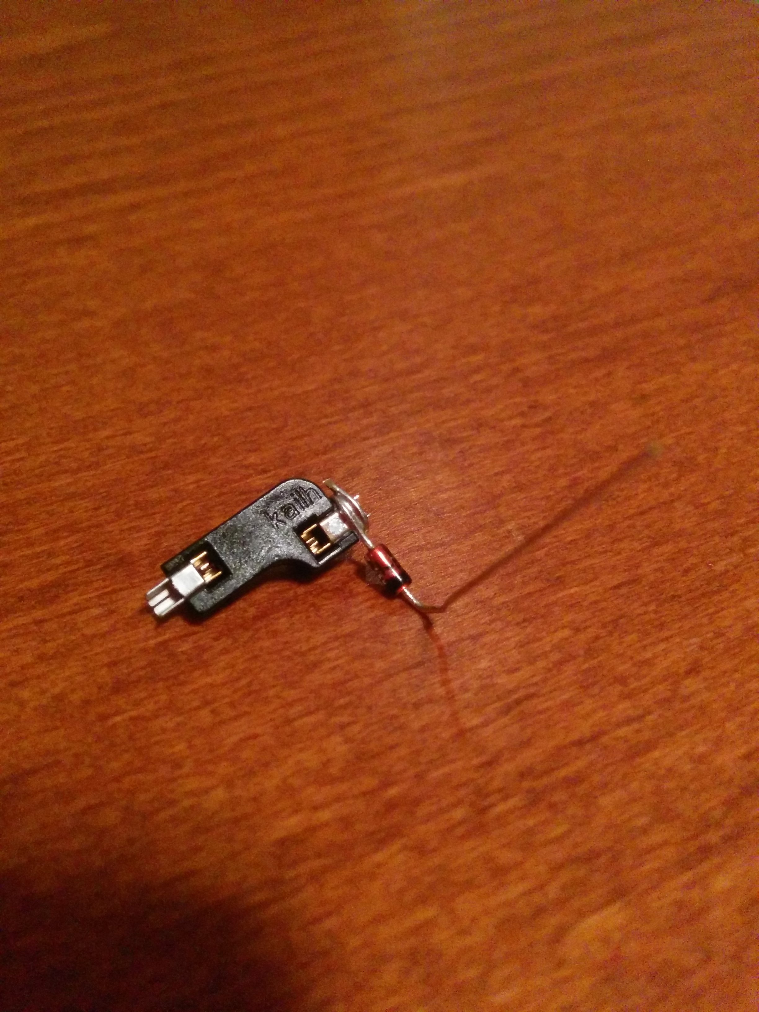
Normally, the first step of assembling a keyboard is to mount the switches to the plate, and then solder diodes to the switches. The beauty of using Kailh hotswap sockets is that, instead, I could just solder the diodes to the sockets first! This made the job a lot more pleasant, since I could wrap the diode around the socket, put the whole thing on a helping hand, solder, then mount the socket on the target switch.
Initially I tried slipping the diode lead through the break in the hotswap socket lead, only to discover that doing so spread the socket contacts and cause it to no longer hold tight to the switch! Realizing this, I altered my plan and instead wrapped the diode lead around the socket lead, then soldered the whole thing together. You can see the result here:
Critically, it was important, for the first diode, to place the socket on the switch, verify which side would be connected to the row, and then use that to determine on which side the anode would be placed. After that I just had to be consistent.
I also made sure to bend the opposite lead (in the opposite direction!) to support later soldering the magnet wire to diodes. All leads were bent using a lead bending tool to ensure consistency in the bends. Below you can see the completed work product:
Throughout this work I made sure to use a multimeter to test every diode before soldering, and every socket after soldering. I also tested every switch though, since I was using hotswap sockets, this was a lot less important! This validated that the socket, switch, and diode were working and arranged correctly.
And good thing, too! I soldered one diode on backwards…
Session 2a: Matrix design and pin assignment
The keyboard matrix ties the switches into a set of rows and columns, which are then soldered to pins on the controller. This requires the design of keyboard matrix itself (since you need to decide how the switches will be assigned to the matrix positions), along with a pin assignment (to determine which pins on the controller will represent each row and column).
Fortunately, there is an online QMK Firmware Designer that includes an interactive tool for both of these tasks, with the added bonus that it will attempt to automatically build a matrix (which I then heavily altered), and can generate a QMK source bundle that is configured with the specified design!
Thus, armed with the Itsy Bitsy AVR pinout diagram, I was able to produce the following matrix design:
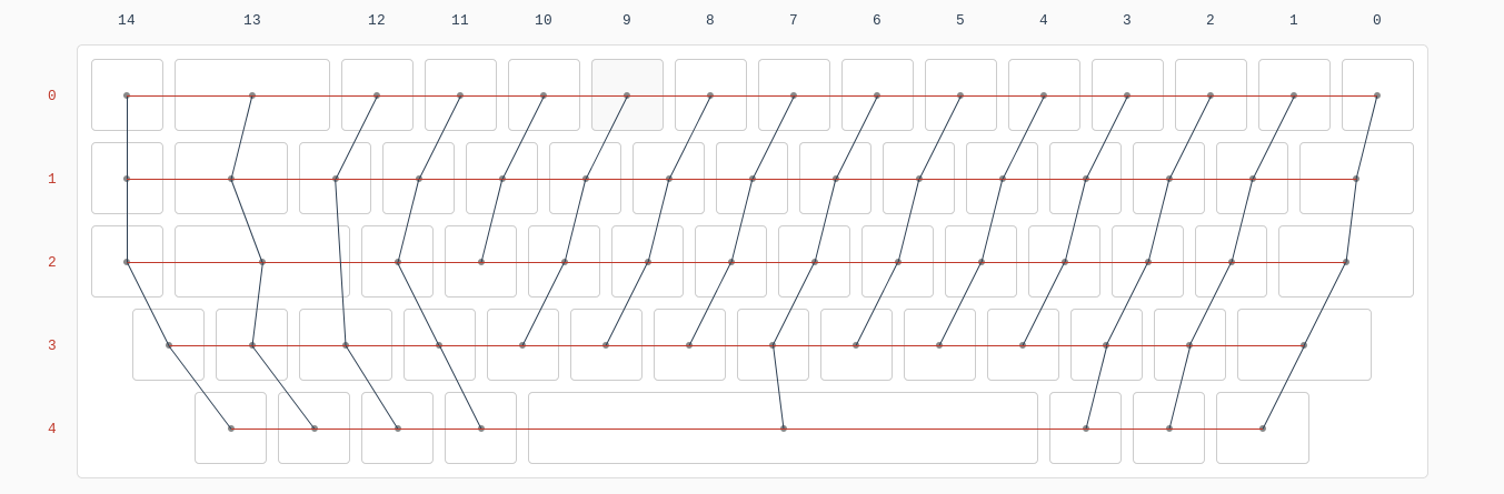
Assigned to the pins as follows:

A huge shout-out to the authors of this firmware builder, as it made it infinitely easier to get my matrix layout just right!
Session 2b: Controller pins
As I mentioned previously, rather than soldering wires directly to the Itsy Bitsy or even to a set of header pins, I decided to make use of a set of board mating sockets. As a result, the very first thing I had to do was solder sockets to the pins assigned to my matrix. You can see the arrangement here:
At this point I could’ve chosen to solder the switches together into a matrix, and then solder the matrix to the controller. However, I was concerned that, if I did that, I’d have trouble cleanly routing the wires back to the controller.
As a result, I decided to work the other way, attaching the wires to the controller, and then soldering the switches into a matrix using those wires.
This worked incredibly well!
To attach the wires to the controller, I chose to solder wires to the associated pins I would be using with those sockets. And here is where I made a minor mistake: Thinking it would be safer, I decided to start soldering the wires to the pins without first mounting the pins in the sockets (similar to how I attached the diodes to the sockets). As a consequence, the pin header warped due to the heat of the soldering iron!
I discovered this warping part way through the soldering job and realized I needed to install the pins in the sockets, and then solder (as the socket would keep the pins straight). Fortunately, with a bit of force, I was able to get the socket onto the board and finish the work. Lesson learned!
The soldering itself was done by scraping the enamel off the wire with a knife to form a lead, bending the lead into a hook around a spare set of pins, trimming off the extra length, and then attaching the lead to the pin.
The final work product can be seen here (this photo was taken after I began assembling the matrix, but you can see how the wires are attached and routed):
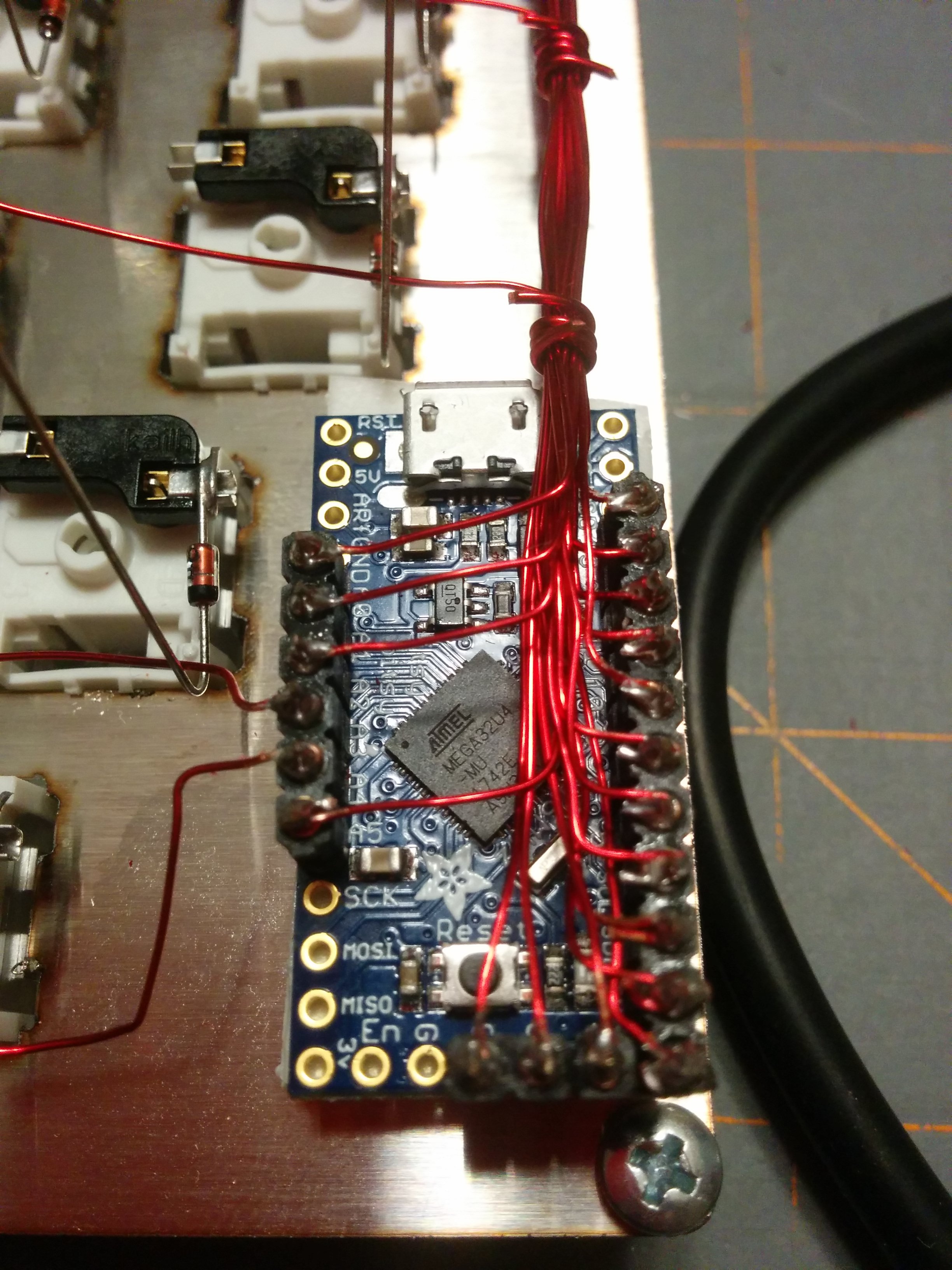
And please, no messages about my filthy soldering job, here… I’m just amazed there aren’t any shorts!
You’ll note that two of the wires are facing away while the rest of the wires are facing inward and routed so they can be bundled together. As I completed the column wires, I tested laying the controller in the case to see how the wires would best be routed. In this way I noted that two of the rows would best be routed as shown in the image, while the rest would be routed together.
Throughout the work, I made sure to test every wire to verify I’d scraped off sufficient enamel, tested every joint after soldering, and tested adjacent pins to ensure no shorts. And, of course, I tested the controller after assembly to ensure I hadn’t fried the thing somewhere along the way…
I will say, this was hands down the most tedious part of the job. Due to the delicacy of the work I really had to take my time. Scraping the enamel off the wires was time consuming and error prone. Forming the leads required a fine touch. Trimming the excess had to be done extremely carefully. Then, as the work progressed, the wires became increasingly irritating to manage. I easily spent the same amount of time soldering the 20-ish pins as I did assembling the 60-ish sockets!
Session 3a: Matrix construction
With the controller connected I could move on to the main event: assembling the matrix itself!
To keep the work as clean as possible, I used 22 AWG magnet wire to bundle the wires together (in hindsight I could’ve used zip ties, but I liked the look of the final result!) In each spot where I needed to peel away a wire, I wrapped the bundle, which kept everything neat and tidy.
I began by first mounting the controller to the case itself. How? Using 3M Command adhesive strips!
This versatile little product provides two velcro-style strips, which mate to one another, combined with an incredibly strong adhesive. Using this product I could mount the controller to the plate while still allowing me to easily remove or slightly reposition it.
Handy!
It was also no accident that the key layout I designed made for ample space to mount the controller to the plate, as normally it would have to be positioned under the spacebar, or somewhere beneath the switches themselves.
With the controller in place, I could assemble the switches into rows.
To do so, each row wire was laid across the (bent) lead of the diode. The diode lead was then folded to form a tight loop around the wire. I then soldered the wire to the lead using a hot soldering iron (which burnt away the enamel coating). Finally, I trimmed off the excess lead. You can see the final work product here:

Once the rows were completed, I then moved on to the columns. To assemble those joints, starting from the top of the column and working down, I wrapped the magnet wire around the socket lead tightly and then soldered to form the joint. The picture below show the completed matrix:
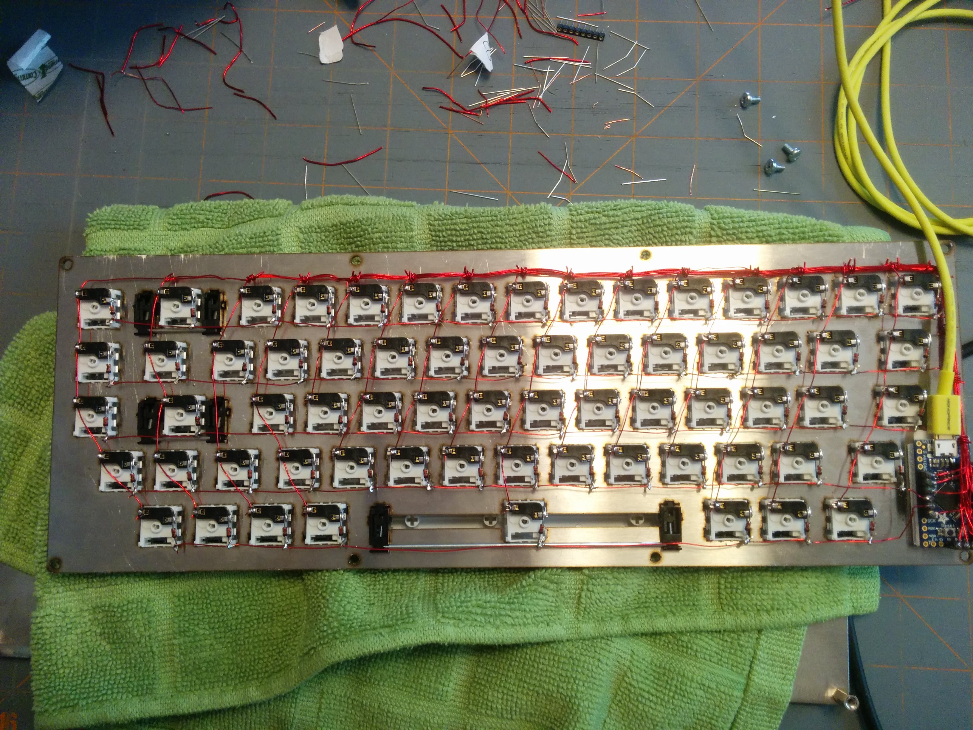
Of course, throughout the work, I tested the connection between the switch socket and the pin on the controller (though I must’ve missed one or something, as later I did discover a single bad diode on the control key that had to be replaced)!
It was here that I discovered an unexpected problem: the use of the sockets on the controller board resulted in the combined height of the controller, sockets, pins, and wiring to exceed the 10mm space I’d planned for the interior of the case.
I couldn’t complete assembly of my keyboard!
As a result, I had to put in an order for 15mm standoffs that would provide the space I needed, a mistake that lead to the one week delay in the assembly of the project…
Session 3b: Firmware
The interactive keyboard firmware designer provided me with a base firmware image I could work with, but not trusting the recency of the code it used, I chose to clone the QMK repository, copy over the layout to the QMK codebase, and build from an up-to-date tree.
I then applied a few tweaks and customizations to the firmware, altering the function layer a bit, switching the ESC key to a GESC hyper key, and so forth. Then I built the image and I was ready to write the firmware!
The only difficulty was in the flashing itself.
The QMK build instructs the user to connect the controller to the PC, then reset the board to load the bootloader, after which flashing progresses using avrdude.
However, I immediately encountered errors indicating that avrdude couldn’t talk to the controller (timeout errors of some kind).
After furiously scouring the internet for a solution to the error messages I was seeing I thought I might have been at an impasse, which would have been enormously disappointing. I spent so much time on this project already!1
Fortunately, I then decided to, you know, read the documentation, and the answer immediately presented itself.
It turns out that the Itsy Bitsy reset button must be pressed twice to enter the bootloader, and not just once.
Doh!
Once I followed the documented instructions, the flash proceeded successfully, and I pressed my first key. The letter ‘I’. And there, on the terminal, I saw it:
lappy:~$ i
Then, for kicks, I checked syslog:
usb 1-2: new full-speed USB device number 25 using xhci_hcd
usb 1-2: New USB device found, idVendor=feed, idProduct=6060
usb 1-2: New USB device strings: Mfr=1, Product=2, SerialNumber=3
usb 1-2: Product: keyboard
usb 1-2: Manufacturer: thebark
usb 1-2: SerialNumber: 0
input: thebark keyboard as ...
Mind blown!
I then tested the rest of the keys. And it worked! It all worked.
I have to honestly admit I was completed astonished. The fact is, as a programmer, the idea of something working the first time is utterly unheard of. Every programmer has experienced the feeling of code functioning on the first try and immediately furiously debugging to find that hidden error that must exist. It’s incredibly unnerving!
Now, given the amount of testing I performed along the way, I suppose I shouldn’t be totally surprised.
But I am certainly surprised a little!
Edit: And if you’re looking for the firmware for this project, check out my fork of the QMK repository on Github.
Session 4: USB breakout board and cable
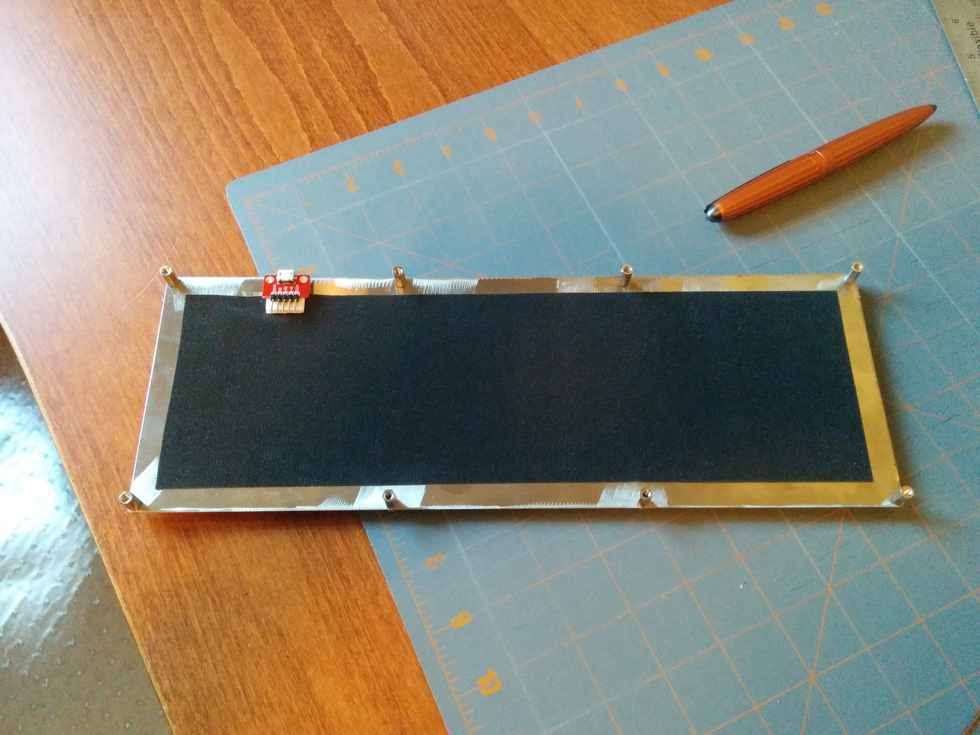
While waiting for the new standoffs to arrive, I decided to assemble the USB breakout board and cable, and attach the foam to the bottom plate of the case.
To once again avoid soldering wires directly to pins, I attached a right angle pin header to the breakout board. I then built a custom cable, which would attach the USB port on the controller to the breakout board by cannibalizing a micro USB cable and wiring it to a compatible pin socket.
At this time I also cut the liner foam to fit the case, including a small cutout where the USB breakout board would be mounted, and attached it to the case using double-sided tape.
And how did I mount the breakout board?
You guessed it: 3M Control adhesive strips! What can’t they do?
You can see the breakout board and back plate here:
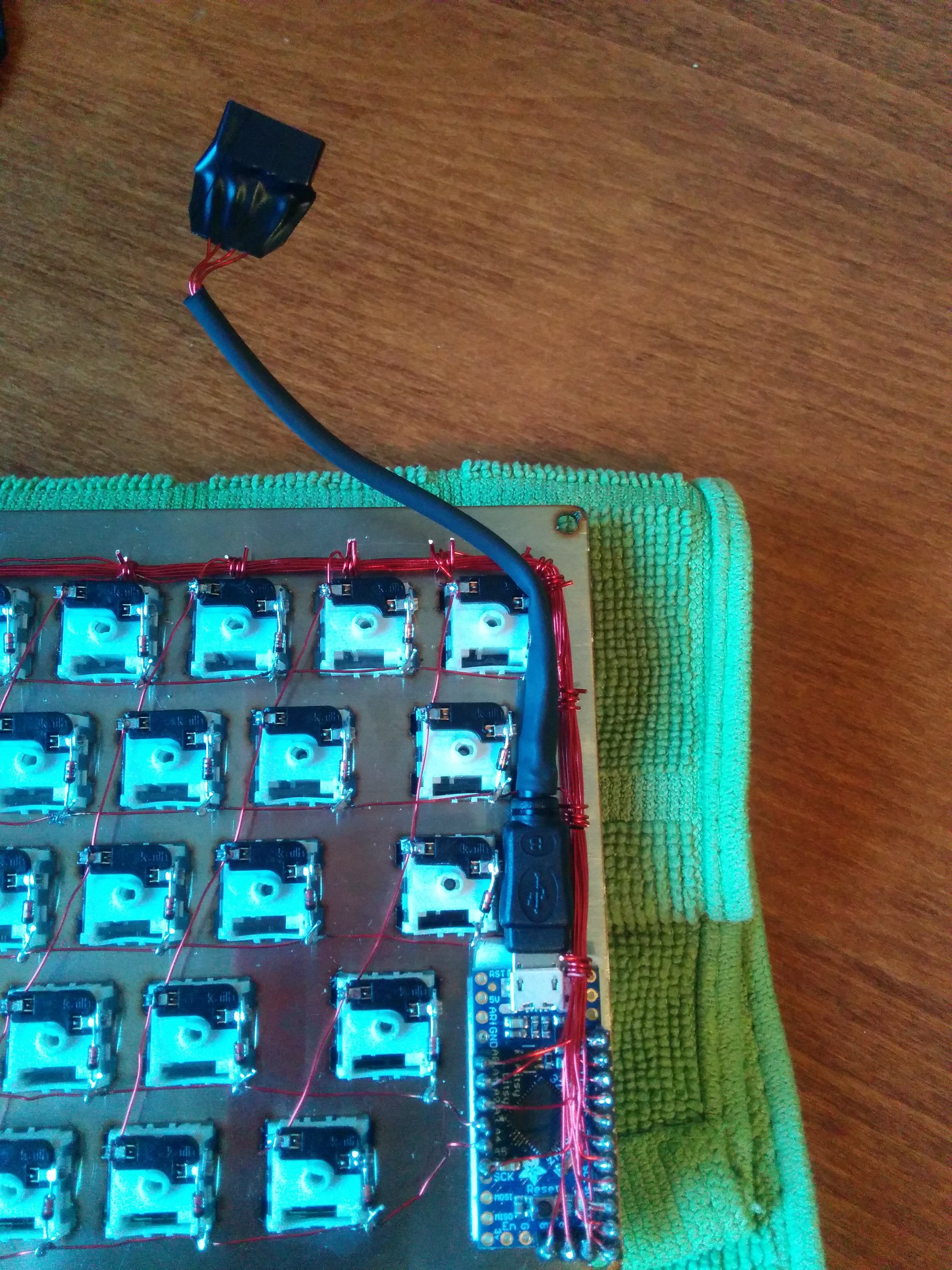
And here, you can see the custom cable attached to the controller:
Obviously, throughout this work, I tested each connection and performed a final test by connecting the keyboard to my laptop through the breakout board. Yup, that also worked perfectly!
Session 5: Final assembly
Due to the wait for the standoffs, plus an intervening work trip, it wasn’t until the following Friday that I was able to complete final assembly of the keyboard.
First, I needed to attach the keyboard feet to the bottom of the backing plate.
Yes, once again, I used those 3M strips! Now, I must admit, it was here that I made a bit of a mistake. I ordered some new strips from Digikey, thinking I was picking up the adhesive velcro versions, only to discover that, no, I only picked up the double-sided adhesive versions.
Oh well! They still work, even if the setup isn’t as adjustable as I’d like.
You can see the feet mounted to the case in the picture below:
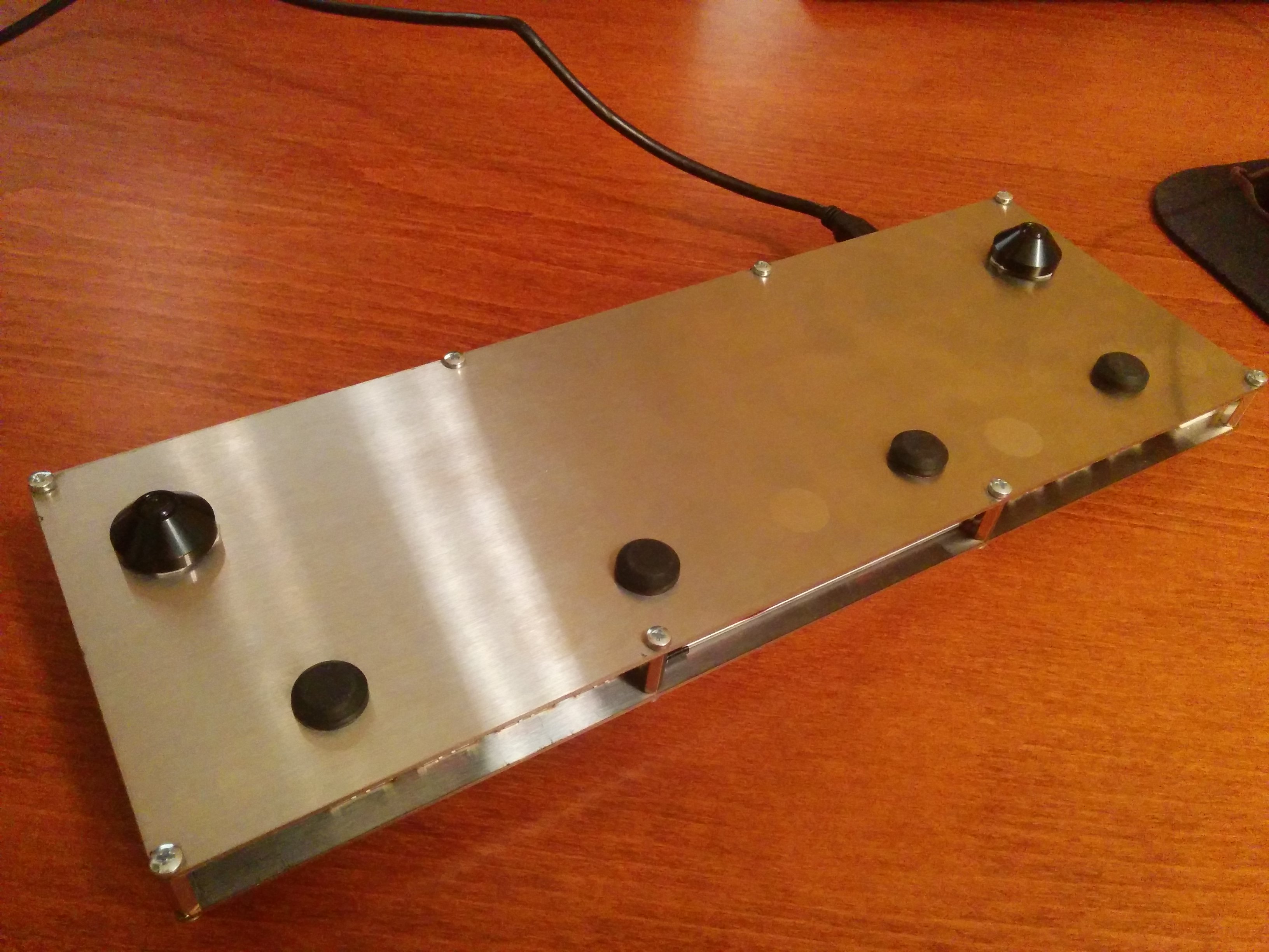
With the feet attached, I could take the final step: assembling the case with the new, 15mm standoffs I’d acquired.
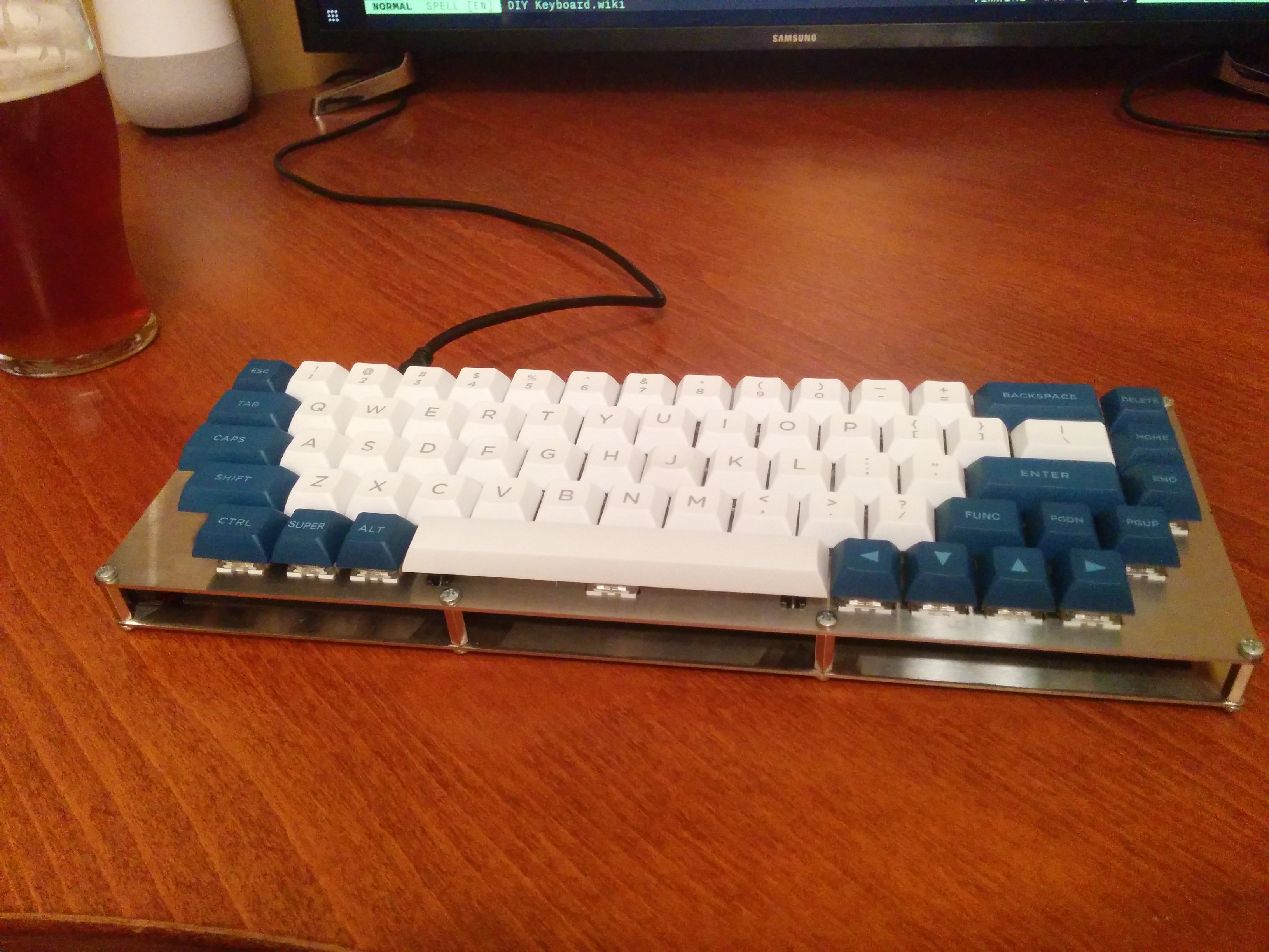
And here it is, the final product!
-
In hindsight, I should’ve tested flashing the firmware to the Itsy Bitsy before ever proceeding with the build to ensure no surprises at this stage in the project. ↩
Handwired Alpha - First impressions and retrospective
First impressions: Overall, fantastic!
Now, it ended up being a fair bit thicker than I’d planned, which means the keys are higher than I’d like, and that leads to slightly annoying ergonomics (though after comparing to a couple of other keyboards I have on hand, in reality, my wrist placement doesn’t end up changing much, so I think it’s fine). And the stabilizers rattle a fair bit, a problem I plan to remedy with a little grease (and as an aside, that fix wouldn’t be possible that I not gone with a hotswap build, as lubricating stabilizers requires switch removal… so… yay!)
Edit: I greased the stabs under the Space, Enter, and Backspace keys and man, what a difference! The keyboard has a nice, consistent sound, now! And, as a side benefit, I got to see how easy it would be to hotswap the switches on this thing, and as expected, it works great!
But man. It’s solid as all heck, with a nice heavy thock with each keypress. The Kailh Hako Violet switches are fantastically smooth and have just the right amount of tactility. And the keycaps turned out to be very nice.
Ironically, at nearly the exact same time I was finishing this build, the Keycool 84 2s that I picked up on Massdrop arrived, and now, comparing the two, I can’t help but be a little disappointed with the Keycool. The general feel of the Alpha is so much more sturdy and solid compared to the plastic on the Keycool. Oh well!
The two biggest challenges with the layout are the control key position (which I’m slowly getting used to), and the exclusion of the function row, which leaves some of the keys less accessible. Now, if this board was going to be a daily coding driver that’d be a problem; the biggest challenge is the fact the tilde key is buried under the ESC key in a function layer. But coding isn’t the primary use case for this keyboard, so I don’t think it’ll be a problem in practice.
So, all things considered, for a first build, this thing has been a fantastic success!
Of course, these are just first impressions.
It’ll be interesting to see how this keyboard fares at work with a solid week’s worth of mileage on it. At minimum, I could see needing to alter the firmware a bit to optimize the key mapping. Fortunately, QMK is so darn flexible I could make this thing do anything I wanted.
And the switches are a very different animal from the Browns I’ve been using day-to-day at work. The tactile bump requires some additional force to overcome, and the spring weight definitely increases on the down stroke. So it’ll be interesting to see if I find this board fatiguing in the long run (though, again, if it turns out the Violets just don’t work for me, I can always replace them!)
As for the project itself, I gotta say, it really was a surprisingly rewarding experience. The feeling when that first key press worked exactly as planned was incredibly difficult to describe; I suspect I felt the same way when I wrote my first working computer program.
So, while it definitely wasn’t the cheapest of projects (oy… not by a long shot), I do think it’s been a heck of a fun challenge to take on! Now here’s hoping I get years of mileage out of this thing!